Back to search
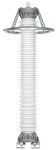
TEXLIM Q096-CN145
This surge arrester provides protection for switchgear, transformers and other equipment in high voltage systems against atmospheric and switching overvoltages.
Especially suitable for applications where:
– The installation location is in an area with high lightning intensity and high energy requirements
– Grounding or shielding conditions are poor or incomplete
– The seismic level is considered extreme
The TEXLIM Q-C is superior where low weight, non-fragility and additional personnel safety is required.
General data
Unit
Neutral ground arrester
Yes
Family name
TEXLIM
Type designation
Q096-CN145
Design
MO, Gapless
Manufacturer country
Hitachi Energy, Sweden
Maximum system voltage (Us)
kVrms
145
Arrester classification as per IEC 60099-4 Ed. 3.0
Class
Station; SM
Nominal discharge current
kApeak
10
Rated voltage (Ur)
kVrms
96
Maximum continuous voltage (Uc)
kVrms
-
Frequency
Hz
15-62
TOV capability (after thermal energy rating Wth)
1s
kVrms
104
10s
kVrms
98,9
Charge, energy and current withstand data
Repetetive charge transfer rating Qrs
C
2
Thermal energy rating Wth
kJ/kV (Ur)
8
Discharge current withstand strength
High current, 4/10 μs
kApeak
100
Low current, 2000 μs
Apeak
1000
Repetitive charge transfer test value (IEC) - sample tests on all manufactured block batches
C
2,7
Energy data as per previous IEC standard IEC 60099-4, Ed 2.2
Line discharge class
Class
3
Energy capability - thermal energy capability (as per IEC 60099-4 Ed 2.2, clause 8.5.5)
kJ/kV (Ur)
8
Guaranteed max. protective data
Maximum residual/discharge voltage with current wave 30/60 μs (slow-front/switching)
0.5 kA
kVpeak
185
1.0 kA
kVpeak
191
2.0 kA
kVpeak
198
Maximum residual/discharge voltage with current wave 8/20 μs (fast-front/lightning)
5.0 kA
kVpeak
215
10 kA
kVpeak
227
20 kA
kVpeak
249
Maximum residual/discharge voltage with current wave 1/(2-20) μs (FOW as per IEEE, steep front as per IEC) External inductive effects neglected
10 kA
kVpeak
245
Technical data for housing
Short-circuit capability
High current, 0.2 s
kArms
80
Low current
Arms
600
External insulation - Requirements as per IEC 60099-4
LIWL, 1.2/50 μs
kVpeak
294
50 Hz, wet (60 s)
kVrms
143
SIWL, wet (250/2500 μs)
kVpeak
238
External insulation - Sum of tested values on individual empty unit housing
LIWL, 1.2/50 μs
kVpeak
701
50 Hz, wet (60 s)
kVrms
341
SIWL, wet (250/2500 μs)
kVpeak
592
Creepage distance (nominal)
mm
mm
4800
mm/kV (Us)
mm/kV (Us)
33
Creepage distance class
Not Applicable
Specified long-term load (SLL)
Nm
21000
Specified short-term load (SSL)
Nm
40000
Insulator colour/material
Grey Silicone
Line terminals
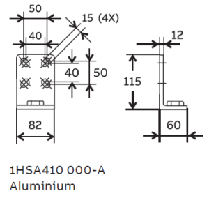
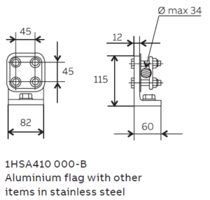
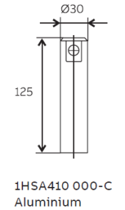

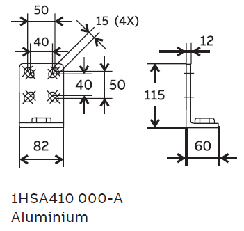

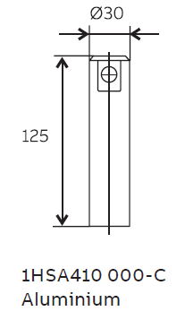
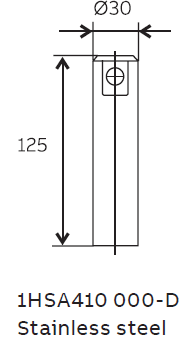
Earth terminals
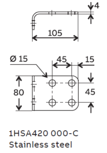
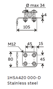


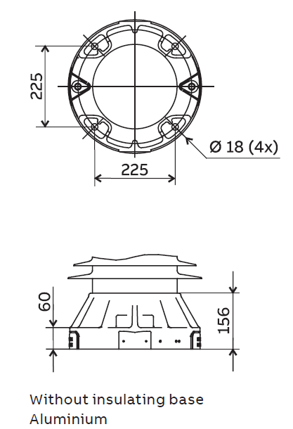
Drilling plans

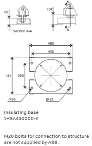


With insulation base
Unit
1-pack
Volume
m3
2,96
Gross
kg
194
2-pack
Volume
m3
2,96
Gross
kg
313
3-pack
Volume
m3
2,96
Gross
kg
432
Without insulation base
Unit
1-pack
Volume
m3
2,96
Gross
kg
167
2-pack
Volume
m3
2,96
Gross
kg
259
3-pack
Volume
m3
2,96
Gross
kg
351
Each crate contains a certain number of arrester units and accessories for assembly and erection. A packing list is attached externally on each crate.
Each separate crate is numbered and the numbers of all crates and their contents are listed in the shipping specification.
Hitachi Energy reserves the right to pack arresters in the most effective/economic combination. Alternate or non-standard crates may
involve additional charges.
The table above is to be seen as an approximation and specific data for deliveries may differ from the values given.
Downloads